
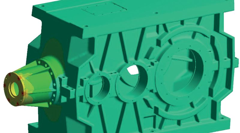
The Influence of the Gearbox Housing Stiffness on the Gear Mesh Load Distribution
The housing stiffness influences the bearinf positions and, therefore, the shaft alignment once the gearbox is subjected to loads. However the housing deformation does not impact directly on the performance of the gears. The meshing conditions are, in fact, influenced by the shaft misalignments, the shaft and bearing deformations and by the gear manufacturing tolerances. In the following study, all these influences are studied and compared to identify those of greater relevance.
by Dipl.-Ing. Jürg Langhart, KISSsoft AG, Dr.-Ing. Ioannis Zotos, KISSsoft AG. Translation by Ing. Massimiliano Turci
The first part of this study focused on the factors impacting on the performances of gears in a gearbox.
A bevel helical gearbox was considered in order to evaluate the various influences such as tooth contact (3.1), shat and bearing deformation (3.2), manufacturing tolerances (3.3), housing deformation (3.4), the relevant details of the housing stiffness matrix (3.5). In the following pages all the other factors will be evaluated.
4 Bevel stage
4.1 Introduction to bevel gear misalignment
Due to the gear mesh force direction governed by shaft offset, pressure angle, pitch cone angle and helix angle (mean spiral angle), the bevel gears will be misaligned. This misalignment is obviously also depending on the support of the gear shafts. The resulting deformations are typically defined along Klingelnberg [9] using VHJ displacement conventions as shown below. Other conventions exist but are not used in this example, Figure 17.
The total of the VHJ displacements are formed from the respective displacement components of pinion and wheel. For the H and J displacement, the axial movement of the gear shaft is relevant. This means that – opposed to the cylindrical gear stages – the axial movement of the shafts is to be considered. Hence, a detailed modelling and calculation thereof is required. The values for VHJ displacements are calculated in KISSsoft automatically from the deformations and displacements of the pinion and wheel shaft. The VHJ displacements are also used to explain the shift of contact pattern in bevel gears. In our example, a LH bevel gear set is used. If the drive flank is loaded, of the displacement of pinion and ring gear results in a shift of the contact pattern towards the heel, Figure 18. In order to avoid the unrequested edge loading due to the unfavorable shift of contact pattern, a longitudinal crowning is applied. If required, the spiral angle is modified too. Further modifications like Bias are not discussed here.
4.2 Methods for assessing the contact patterns
In the strength rating method ISO 10300 [10] for bevel gears, the load distribution as calculated is not directly considered. The load distribution is determined in a simplified manner only, giving rough values for KHβ depending on the type of shaft supports (e.g. overhung gears will result in a higher value for KHβ).
Hence, in the bevel gear strength rating, there is no equivalent procedure to the detailed line load distribution calculation as per ISO 6336-1, Annex E as available for cylindrical gears. The assessment of the contact pattern for bevel gears is typically done on a roll tester. The contact pattern is checked visually whether it is at the desired location and of desiredlength, In KISSsoft, the tooth contact of bevel gears is assessed using a two dimensional LTCA under load. Thereby, the stiffness calculation of the teeth, which is the basis of the LTCA, is calculated according to Weber/Banaschek. This method is based on cylindrical gears and has been successfully adapted for bevel gear calculations. As the tooth contact analysis is able to consider the shaft deformations, the numerical calculation includes also the relative position and alignment of the bevel pinion and gear under load Also, the modifications as crowning etc. are considered.
The results of the contact analysis include – in the same manner as for cylindrical gears – e.g.: Hertzian contact pressure, transmission error TE, line load distribution and others. Also, the maximum line load wmax is determined and, combined with the mean line load wbm it is possible to calculate a load distribution factor KHβ in the same way as for cylindrical gears.
4.3 Influence of bearing pre-tension on the axial position of the gears in mesh
As mentioned above, the axial position of bevel gears needs to be considered in detail (opposed to cylindrical gears, where the axial position is of little relevance) when calculating the tooth contact patterns. The axial position is strongly influenced by the bearings supporting the shaft. In the gearbox studied, the pinion shaft is supported in axial direction by taper roller bearings. Typically, they are assembled with a slight pre-tension in order to achieve a more even load distribution of roller elements in operation. The pre-tension is achieved by shimming. In the KISSsys model, the pre-tension is modeled such that the position of the bevel pinion does not change, that is, the pre-tension is modeled by moving both outer rings by half of the pre-tension amount in opposite directions.
4.4 Support of the axial force on the housing cover
In the gearbox, the axial force from the bevel pinion is supported by the housing through a bearing cover attached to the housing by means of bolts as shown below. To consider this force flow in the housing correctly, a non-linear FEM model is elaborated where contact formulation including friction (assuming a coefficient of friction μ=0.10). In this extended model, the cover and the bolts are included, the bolts have a pre-tension of FV=44.1 kN, Figure 19, left. The master node of the left taper roller bearing is now attached to this cover, Figure 19, right, marked in blue. With this modelling approach, it is possible to lead the axial force over the cover while the radial force is still directly transmitted to the housing, Figure 19, right.
The FEM calculation is now done in two steps. In the first step, the bolt pre-tension is applied, then, the FEM model is linearized and the reduced stiffness matrix is exported. The effect of the bolt pre-tension is in the below deformation plot, Figure 20.
As expected, the deformation calculation in KISSsys using the above modified stiffness matrix yields that the three master nodes, 1, 2 and 3 (located in the centers of the bearing supporting the bevel pinion shaft) have higher axial displacement. However, the effect is minimal and of just a few microns, Figure 21.
4.5 Temperature influence
Due to the different power losses, inevitably present in the gearbox during operation, the gearbox parts will heat up and expand. In this example, it is assumed that the gearbox temperature increases from 20°C to 80°C (for all parts in an uniform manner) resulting in expansion of housing and shafts. It is of interest how the bevel pinion shaft is getting displaced due to temperature effects. For this, the FEM model is calculated in three steps:
• Bolt pre-tension is applied
• Temperature increase is applied
• Model is linearized and stiffness matrix is exported
In this, the housing bores are left free to deform. The resulting bore center / bearing position change is shown in below figure and is reaching a value of 0.85 mm at the highest location.
In the KISSsoft shaft calculations, thermal expansion of shafts is defined with respect to a reference point that remains fixed in the local coordinate system. In case of bevel gears, this reference point is typically selected as the pitch cone apex. For the assumed operating temperature of 80°C, the shafts expand with respect to the pitch cone apex which results in an axial movement of the gears, influencing their VHJ displacement values, see Figure 23. The below contact patterns show two typical operating conditions. The contact patterns are checked at assembly, without load. Housing and other parts temperature is then at 20°C. V and H displacement values are very low and within a few 10 μm. See Figure 24 below, left side. With external torque load applied and in operating temperature of 80°C, the V and H displacement values are V = -0.25 mm and H = 0.21 mm. The contact is slightly moved towards the heel side, see Figure 24 below, right side.
4.6 VHJ-displacement considering housing deformation
The influence of the housing deformation can easily be shown for the bevel gear stage by looking at the VHJ-displacement values. In below Figure 25, the VHJ-displacement values are shown, once with and one without housing deformation. As expected, if the housing deformation is considered through the housing stiffness matrix, the displacements are higher once external loads are applied. However, the influence of the housing is small and do not change the contact pattern noticeably.
4.7 Bevel gear modifications
In the production of bevel gears, gear modifications are often applied by the manufacturer based on experience or general guidelines found in the respective literature. This because the designer typically lacks tools to calculate required and optimal modifications. The designer often has to accept that the modifications are decided by the manufacturer and is left to wonder whether the part machined will fulfill his requirements.
For the Zyklo-Palloid® bevel gear set used in this example, the literature (Klingelnberg) recommends a crowning of 1/350th to 1/800th of the face width for “small” displacements. Often, in practical applications, a value of 1/1000th is used. This would correspond to a crowning value of 84 μm, resulting in the contact to be somewhat on the heel side with a maximum contact pressure of 1360 N/mm2 (Figure 26, left). Assessing the line load distribution by the ratio of maximum line load to mean line load, a KHβ value of 2.7 is found. The peak to peak transmission error is calculated at PPTE = 6.8 μm. With this modification, a contact pattern without edge load and stress peaks is achieved. To maximize the power density of the bevel gear set, the modifications are now optimized. The contact pattern is moved to the center of the flank and the crowning is reduced to 20 μm (Figure 26, right). The resulting contact stresses now drop to 1140 N/mm2, or an improvement of almost 20%. KHβ drops considerably to 1.7 and the peak to peak transmission also is reduced to PPTE = 2.45 μm. We may therefore not only expect an increased load bearing capacity but also a reduced noise level.
4.8 Influence of gear manufacturing tolerances
In ISO 17485 ‘Bevel gears – ISO system of accuracy’, no values for the manufacturing tolerances in lead direction are given, an assessment of the effect of the gear quality on the contact is hence not directly possible. Therefore, as an approach which can be seen in industry as well, the values listed in ISO 1328 for cylindrical gears are used. As a reference, the equivalent cylindrical gear is used to determine the applicable helix slope deviation at fHβ=10 μm for the pinion and 12 μm for the wheel.
A combination using a statistical approach covering 99.7% of all cases results in a total of fHβ= +/- 17.5 μm. This manufacturing error has very little influence on the load distribution when combined with the above optimized lead modifications, see below Figure 27.
4.9 Contact optimization
The above findings are in line with common practice in general gearbox engineering that the housing deformation is not of prime relevance when designing gear modifications. The resulting improvements in load distribution as designed using KISSsoft and KISSsys are shown below, Figure 28.
The focus of this study was to show the influence of the housing deformation on the required modifications. The following figure shows the influence of the housing on the required modifications. These are shown while not considering the housing deformation in blue and while considering the housing deformation in red. It is well visible that out of the total modifications required, the effect of the housing deformation is small in this gearbox / housing design.
5 Summary
The above study illustrates that it is quite a complex task to perform a detailed and accurate calculation considering bearings, shafts, temperature and housing influence on the gear mesh. While it is very simple and fast to consider e.g. gear machining errors or bearing stiffness in the calculations, the integration of housing information takes more time. Still, this may well be justified in critical applications. Considering a compact and stiff housing as used for the industrial gearbox investigated in this study, we find that the housing deformation is not the most relevant factor influencing the gear mesh. Shaft and bearing deformations as well as variations in the bearing clearance, manufacturing errors and thermal influences are more significant. Furthermore, the commonly held wisdom that a soft housing leads to meshing problems is not supported as a soft housing may keep shafts (and the gears) nicely parallel even if the center distance is increased considerably (but due to the nature of the involute gearing, this does not affect the mesh negatively). Even for the bevel gear stage, it was found in this particular design that the influence of the housing deformation on the meshing condition is marginal. Recommendations from literature as to the amount of crowning to be applied were confirmed, they are suitable to compensate manufacturing tolerances and the housing deformation. The bevel gear LTCA function implemented in KISSsoft has again proven itself as a most valuable tool for the assessment of spiral bevel gears in contact. The value of the classical approach, which takes no account of the housing stiffness when designing industrial gearboxes is therefore confirmed.