
Tapered Roller Bearings versus Angular Contact Ball Bearings: a Direct Comparison
This study compares the new generation of Timken Power-Dense, Fuel-Efficient tapered roller bearings with angular contact ball bearings for axle drive pinion shafts.
by Jean Merckling
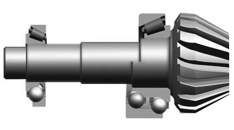
Timken, a manufacturer of bearings and drive technology components, has developed a new generation of fuel-efficient tapered roller bearings with a greater power density. This new generation of bearings can keep up with the efficiency of angular contact ball bearings, even surpassing them in some cases, as shown by comparative tests in the in-house test rig. Today, angular contact ball bearings (double row) have taken a significant market share for pinion bearing concepts over tapered roller bearings due to their high efficiency, especially at 40°C and under NEDC working conditions used to define car CO2 emissions levels. As a continuous improvement, Timken has examined the use of fuel-efficient tapered roller bearings for LVS (Light Vehicle Systems) axles in order to better understand the real efficiency of FE TRBs compared to ACBBs (figure 1). Based on that examination, which was performed in partnership with a leading axle manufacturer, Timken developed a new generation of fuel-efficient tapered roller bearings (FE TRB) that is able to equal angular contact ball bearings (ACBB) in efficiency. This product is a more power-dense type fuel-efficient bearing.
Tests of the new FE TRB solution
Once the Timken bearings were designed and the prototypes built, they underwent a complete test program at The Timken Technology Center (Canton, Ohio, United States) in order to compare their performance and efficiency to that of ACBBs. The first step of the test program evaluated the application under real working conditions. The actual oil flow going to the pinion bearings was measured using the current axle drive and housing designs. The customer rear axle drive was equipped with both ACBBs and new FE TRBs in order to measure the oil flow to the pinion bearings at different pinion shaft speeds and oil temperatures, and the tests were run on both. Based on the oil flow measurement tests, three oil flow rates were selected for efficiency testing on the pinion simulation rig: 0.7 l/min (at 40, 60, 80, and 100 °C), 1.6 l/min, and 2.6 l/min (both at 60, 80, and 100 °C).
Pinion simulation test rig
The company developed a specific test rig (figure 2) and experimental method, leveraging state-of-the-art controls, hardware, and tooling to simulate the pinion’s system environment (load, oil flow, speed, deflection), allowing precise measurement of the bearing torque alone (without axle drives and seals, as with traditional axle efficiency tests). The object of the pinion simulation rig design was to load the bearings exactly as they would be in a real axle drive (axial/radial load). Non-contacting seals were used to minimize their influence on the results. Two sets of pinion bearings were run on the rig; therefore, the total torque of the shaft is 2x (head plus tail bearings). Defined oil flow levels, rig controls, and many sensors were used in order to simulate the bearing working conditions as closely as possible.
Test matrix for torque tests
Together with the partner customer, a full test matrix (figure 3) was defined and run on the pinion simulation test rig to simulate both NEDC as well as more realistic loading conditions. This test matrix was run with defined combinations of test parameters. Each FE TRB and ACBB was run three times to check the consistency of the results and confirm test precision. A massive amount of data was collected, allowing a precise understanding of the bearings’ efficiency.
For each load case of the test matrix (preload/torque/temperature), a speed sweep (ramp up and down) was run from 250 rpm to 6,000 rpm and back to 250 rpm. Torque, temperature, and speed were recorded every half-second. Trend line equations were calculated for each bearing type’s mean torque to allow efficient postprocessing and comparison of the new FE TRBs to the ACBBs. Figure 4 shows the key summary of all the torque measurements, based on postprocessing of all data. Values are the averages of all runs performed with similar loading (three runs and various preload forces) in order to accurately represent the bearing torque. The matrix shows the ratio of FE TRB torque divided by ACBB torque in three categories. Under the conditions indicated in green, the new generation FE TRB performed better. Under the conditions indicated in white, the ACBBs performed better. Figure 5 consists of two examples of torque graphs, showing extracts of torque measurements for the NEDC case (left) and more realistic road loads and temperatures (right).
Torque comparison
In order to assess the respective bearing efficiency for NED cycles, a calculation was done for an assumed NED cycle using the torque measured data of the test matrix.
Calculation results (figure 6) indicate that FE TRB power loss would be similar to ACBB power loss for the given NED cycle, thus demonstrating that the key target of the project was achieved.
Conclusion: similar efficiency under NEDC conditions
The key outcome of all efficiency tests run on this test rig is: the new generation of FE TRBs provides comparable efficiencies to ACBBs under NEDC conditions at 40°C. Moreover, calculations done using test results indicate that these FE TRBs would significantly outperform ACBBs in efficiency at higher temperatures and higher loads. Efficiency tests on both bearing solutions performed by our partner in actual rear axle drives have confirmed these conclusions.
Stiffness tests: better deflection than ACBBs
The pinion simulation test rig also was used to compare bearing and system stiffness. A matrix of loads was defined in order to represent NEDC conditions as well as larger application loads (drive and coast). Shaft deflections were measured in both radial and axial directions at a point representing the pinion gear mesh point. Many sensors were located on the rig in order to get precise and reproducible data. The FE TRBs demonstrated similar or better deflection than the ACBBs, which is key for gear performance and NVH.
Validation of results by means of Syber
This section compares the calculation results made with the corporate Syber tool to the measured torque of the new power-dense fuel-efficient tapered roller bearing. A precise calculation model of the test rig was created in Syber in order to simulate as closely as possible the bearing loading and working conditions of the test rig.
The calculation model demonstrated that the calculated torque is accurate compared to the test results. This means that the company can use its Syber calculation tool to design high-efficiency FE TRB solutions for new customer projects. Repeating the efficiency tests for designs and customer proposals with highly efficient FE TRBs will be unnecessary for future projects and other bearing sizes.
Conclusion
The study objective was to develop and test the new generation of Timken high-efficiency, power-dense fuel efficient tapered roller bearings. The new solution was designed for efficiency and power density (better weight, smaller size), while aiming for performance similar to that of ACBBs. Leading-edge testing methods and test rigs were used, which allowed precise measurement of bearing efficiency in the axle drive simulated environment (oil flow, loads, etc.). Bearing torque tests were run on in-house rigs simulating axle drive pinion bearing loading. Measurements were made according to a test method based on the New European Driving Cycle (NEDC). The Timken-implemented test program and the corresponding results showed that the new, fuel-efficient new generation solution provides comparable efficiency to angular contact ball bearings for NEDC at 40°C. Tests also indicate that this solution’s efficiency is better than that of angular contact ball bearings for many real operating conditions such as loads and temperatures higher than NEDC. The rig used for efficiency testing was equipped with deflection probes in order to measure the radial and axial deflection at the pinion gear mesh location, and to confirm similar stiffness for the new solution. A calculation with the Syber bearing analysis program was performed in order to demonstrate that calculated torque is accurate versus test results. This means that the company can develop new bearing solutions for customer projects without repeating the efficiency tests for every new project.