
The Influence of the Gearbox Housing Stiffness on the Gear Mesh Load Distribution
The housing stiffness influences the bearinf positions and, therefore, the shaft alignment once the gearbox is subjected to loads. However the housing deformation does not impact directly on the performance of the gears. The meshing conditions are, in fact, influenced by the shaft misalignments, the shaft and bearing deformations and by the gear manufacturing tolerances. In the following study, all these influences are studied and compared to identify those of greater relevance.
by Dipl.-Ing. Jürg Langhart, KISSsoft AG
by Dr.-Ing. Ioannis Zotos, KISSsoft AG
Translation by Ing. Massimiliano Turci
The housing stiffness influences the bearing positions and therefore the shaft alignments once the gearbox and therefore the housing is subjected to loads. However, the housing deformation does not yet allow for an assessment of the performance of the gears in terms of e.g. load distribution or vibration. Further to the shaft misalignment caused by the housing deformation, the shaft and bearing deformations as well as gear manufacturing tolerances influence the meshing conditions. (*)
1. Application example
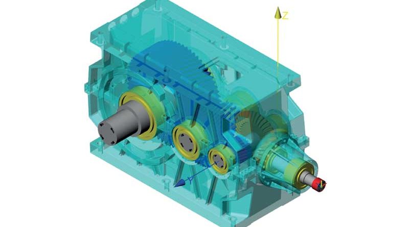
Let us consider a bevel helical gearbox, currently in production by KISSLING AG of Switzerland. Nominal power is 600 kW and the gearbox is operated in a temperature of 45°C to 60°C, with peaks up to 80°C. The highspeed side gears and shafts may have slightly higher temperatures during operation. The cast housing is made of EN-GJS 40.3 and features a number of ribs to make the housing lightweight yet stiff. Considered in this study are the bevel gear stage and the parallel shaft stages. The parallel stages are achieved using helical gears with normal module mn = 8 mm (intermediate stage) and mn = 12 mm (output stage). The gears are ground after case carburizing to a quality grade of Q=6 along ISO 1328 or better. The shafts are supported by two spherical roller bearings each.
The spiral bevel gear stage is a having a ratio of 17:37 with a wheel outer diameter of 460 mm, manufactured as a Zyklo-Palloid® set. The pinion shaft is supported by a paired taper roller bearing and a spherical roller bearing while the wheel shaft is supported by two spherical roller bearings.
2. Procedure
It is of interest to find out the influence of different factors on the required gear modifications. The gear modifications are then assessed using a numerical LTCA (loaded tooth contact analysis) as well as along ISO 6336-1, Annex E (for the calculation of the line load along the face width). The following factors are considered:
• Influence of shaft and non-linear bearing deformation
• Influence of manufacturing tolerances (of gears and of housing)
• Influence of housing deformation
• Influence of temperature at 80°C
A realistic modeling of the shaft displacement and the shaft deformation (which then leads to a gear misalignment) in radial and axial direction is required to calculate the gaping in the gear mesh along ISO 6336-1, Annex E and the resulting contact stress distribution and transmission error.
The axial component of the gear misalignment is not so relevant for parallel shaft gears but for the bevel gear stage as this influences the H displacement (for the pinion) respective the J displacement (for the gear). For bevel gears, thermal growth and axial bearing deformation are most relevant and require attention.
3. Investigation of the parallel shaft stages
3.1 Methods for the assessment of tooth contact
A tooth contact assessment should be done in two steps. Firstly, a line load distribution along the face width, based on ISO 6336-1, Annex E calculation should be performed. Then, a holistic assessment of the contact force in the whole plane of action using a LTCA (loaded tooth contact analysis) should follow.
For the assessment of the face load distribution, the calculation of the line load w [N/mm] along ISO 6336-1, Annex E [1], is recommended. It yields realistic values for the load distribution, a KHβ value needed for the strength rating and consumes little calculation time only. This method may be considered a one-dimensional LTCA and has been described in the context of its implementation in KISSsoft before [2].
A matter of discussion is whether load factors like KA or KV should be considered in the calculation of the line load distribution. This is currently (second half of 2016) being discussed and reviewed in the respective ISO committee (TC 60). In KISSsoft, the educated user may choose how to consider additional load factors in the line load calculation in the settings [3].
A more refined method is the two dimensional LTCA, where also the effective contact ratio under load is considered [4]. It also yields results like transmission error TE, peak to peak transmission PPTE, local power losses due to friction, local contact temperature, local lubricant film thickness, micropitting risks values and others. The two dimensional LTCA also yields a more accurate line load distribution compared to the ISO 6336-1, Annex E method, as it does consider the true contact ratio which is affected by the tooth deformation (this effect is not considered in the one dimensional LTCA along ISO 6665-1, Annex E calculation where the theoretical contact ratio is considered only).
It is therefore obvious that the two methods may yield different results for the load distribution. However, once the appropriate modifications are applied, the differences are small. It is hence recommended to first design modifications based on the values elaborated using the ISO 6336-1, Annex E (which is very fast to use) and then to use – for a final check and for the profile modifications – the two dimensional LTCA (Figure 2).
3.2 Influence of shaft and bearing deformation
The below investigations are documented for the output stage. There, the influence of the shaft deformation influence is studied first. The shaft deformation is a function of shear, torsion and bending loads and is calculated with a semi-analytical method using a Timoshenko beam model. Then, the non-linear bearing stiffness is considered by looking at each contact between a rolling element and the races along [5].
The compression of the rolling elements results in a displacement of the inner ring with respect to the outer ring. In this, also the bearing operating clearance (as a function of bearing clearance, fit on shaft and in housing, thermal expansion and centrifugal effects) is considered.
The housing deformation is not yet considered means the bearing outer ring are in the theoretical positions.
A proposal for an optimal lead modification is provided by KISSsoft based on an algorithm along ISO 6336-1, Annex E. For the parallel shaft output stage, a helix angle modification of cHβ = -11 μm and a crowning of cβ = 19 μm is calculated (Figure 3).
The line load distribution wb with the mentioned influences is shown in Figure 4, left. In Figure 4, right, the resulting line load distribution wb with the mentioned influences and modifications applied is shown in comparison. The face load distribution factor KHβ drops from KHβ=1.17 (without modifications) to KHβ=1.01 (with modifications) what confirms the suitability of the modifications proposed by KISSsoft.
3.3 Influence of manufacturing tolerances
Further to the shaft and bearing deformation, the influence of manufacturing errors is to be considered. Said errors may in fact be the governing factor when determining the gear misalignment as well as suitable modifications to compensate those, they must therefore not be neglected. In general, two groups of tolerances are considered
• Helix slope deviations f Hb of the gears
• Shaft inclination and deviation errors fSb, fSd
Helix slope deviations along ISO 1328 [6] are related to the gear quality and hence influenced by the manufacturing process, Figure 5. For the gearbox considered here and the output stage with mn=12 mm, the permissible helix slope deviation is fHb=15 ¼m for the pinion and fHb=16 ¼m for the wheel. In KISSsoft, these two values may be considered in a worst-case scenario (resulting in a total misalignment of the flanks of 31 ¼m) or in a statistical approach considering a probability of that 99.7%, which results in 22 ¼m misalignment. The later approach is used here. Shaft alignment tolerances along ISO/TR 10064-3 [6] define permissible deviation and inclination errors with respect to the bearing span or gear face width (Figure 6).
ISO/TR 10064-3 determines permissible values for the above deviations from a permissible flank line error Fβ, considering the bearing span L and the common gear face width b as follows:
The above components are combined to represent a misalignment in the plane of action, fΣ:
Values for the bearing span L, common face width b and permissible flank line deviation Fβ are calculated based on the drawing data yielding a deviation error of fΣβ = 30 μm and fΣδ = 59 μm. The resulting misalignment in the plane of action is then fΣ = 50 μm. Again, this is a worst case approach, while a statistical approach yields a value of fΣ = 33 μm, the later is used.
Alternatively to the tolerances as per ISO/TR 10064-3, position tolerances from the drawings (or measured values) may be used, Figure 7.
To compensate manufacturing errors, the use of helix angle modifications is not suitable as those errors are random by nature. To compensate random errors, either a lead crowning or a symmetrical end relief is required. The optimal lead crowning value is calculated by defining a range defining a lower and upper limit and a step size. The different crowning values are then combined with the above, constant helix angle modification of cHβ = -11 μm. In our example, ten different crowning values (minimum at 19 μm, maximum at 55 μm) are created and combined with the constant helix angle modification, Figure 8.
From the above calculations, comparing the face load factor for each of the ten solutions (solution no. 0 is the one without any modifications for comparison), we find that the face load factor KHβ is minimized if the lead crowning is applied with cHβ = 43 μm, Figure 9.
A final check with these modifications, considering all combinations of the flank line error fHb and the shaft misalignment error fma (+fma +fH², +fma -fH², -fma +fH², -fma -fH²) shows that the modifications are most suitable to compensate both shaft/bearing deformations as well as random manufacturing errors. Under all conditions, dangerous edge loading is avoided, Figure 10.
We conclude that the required modifications are cHβ = -11 μm and cHβ = 43 μm. In below Figure 11, these values are shown together with the crowning of cHβ = 24 μm reqruied to compensate manufacturing tolerances.
The resulting face load factor varies between KHβ=1.07 and KHβ=1.16, depending on how the random manufacturing errors are combined. Both values are acceptable considering that the resulting design is “robust”, meaning, it is suitable for any combination of manufacturing errors within the specified tolerances.
3.4 Influence of the housing deformation
Now, the influence of the housing deformation shall be considered. As bearing forces act on the housing and result in a deformation, the bearing (outer) ring are displaced with respect to its original position.
The deformation of the housing is calculated inside KISSsys by using a reduced stiffness matrix of the housing and the mentioned bearing forces (compiled into a bearing force vector). The housing stiffness matrix is generated and exported from the FEM software (ABAQUS, ANSYS or NASTRAN).
An iterative calculation is required as the housing deformation influences the shaft calculation. These result in new bearing forces, which again influences the resulting housing deformation, Figure 12. The approach as implemented in KISSsys has been presented earlier in [8].
3.5 Relevant details of the housing stiffness matrix
In the FEM model of the housing, the bearing centers need to be modeled with a single node, connected to the surrounding bearing seat using e.g. RBE2 or RBE3 type elements (depending on the FEM code used). A simplification due to the modeling is to be accepted also because radial and axial forces are in reality supported by different surfaces.
In the gearbox shown here, the shafts of the two cylindrical gear stages are supported by spherical roller bearings. Their inner ring is using a p6 fit on the shaft and the outer ring a J6 fit on in the housing. The transition fit in the housing will result in the axial loads being transmitted by the shoulder shown below (red path) while radial loads are transmitted directly into the housing walls (green path).
In the FEM model, the spherical roller bearing is supported only on the radial surface, resulting in a somewhat to stiff model for the axial forces. However, as the axial displacement of the shaft is not having a significant influence on the mesh of cylindrical gears, this modelling approach is acceptable.
After importing the reduced stiffness matrix into KISSsys, the matrix is aligned with the KISSsys model by matching the centre of the bearings in the KISSsys model with the nodes located at the bearing centers in the FEM model. Then, the kinematic calculation is executed in KISSsys, the bearing forces are calculated and the bearing force vector is multiplied with the housing stiffness matrix giving a bearing displacement vector. Before assessing the influence of the housing deformation on the gear meshes, let us look at the resulting housing deformations as calculated in KISSsys for the shafts no. 3 and no. 4 (output shaft). Figure 15 shows the total radial displacement of the shaft without (blue) and with consideration of the housing deformation (red). In both cases, the movement of the bearing inner ring with respect to the outer ring due to bearing operating clearance and deformation is considered. We observe that the change in shaft displacement is less than 10 μm when we also consider the housing deformation. As the change in shaft displacement is small once the housing deformation is considered, the required change in the gear flank modifications will also be small. In the example considered, the required change in helix angle modification is only ΔcHβ = -2 μm to compensate the change in the gear alignment. This change has no practical relevance and is well within any manufacturing tolerances. The required total helix angle modification is now cHβ = -13 μm and cβ = 43 μm, Figure 16.
Finally, we may conclude that for the output stage, the influence of the housing deformation is not significant in this example where the housing was well design and is hence stiff.